2812
Generalized Framework for Homogeneous Ultra-High-Field Brain Imaging1Siemens Healthcare GmbH, Erlangen, Germany, 2Department of Neuroradiology, University Hospital Erlangen, Friedrich-Alexander-Universität Erlangen-Nürnberg (FAU), Erlangen, Germany, 3MR Research Collaborations, Siemens Healthcare Limited, London, United Kingdom, 4Department of Biomedical Engineering, School of Biomedical Engineering and Imaging Sciences, King’s College London, St. Thomas’ Hospital, London, United Kingdom, 5Center for the Developing Brain, School of Biomedical Engineering and Imaging Sciences, King’s College London, St. Thomas’ Hospital, London, United Kingdom, 6Imaging Centre of Excellence, University of Glasgow, Glasgow, United Kingdom, 7MR Applications Predevelopment, Siemens Healthcare GmbH, Erlangen, Germany, 8Siemens Medical Solutions USA, Inc., Rochester, MN, United States, 9Department of Computer Science, Friedrich-Alexander-Universität Erlangen-Nürnberg (FAU), Erlangen, Germany, 10Advanced Clinical Imaging Technology, Siemens Healthcare AG, Lausanne, Switzerland, 11Department of Radiology, Lausanne University Hospital and University of Lausanne, Lausanne, Switzerland, 12LTS5, École Polytechnique Fédérale de Lausanne (EPFL), Lausanne, Switzerland, 13Wolfson Brain Imaging Centre, University of Cambridge, Cambridge, United Kingdom, 14Institute of Radiology, University Hospital Erlangen, Friedrich-Alexander-Universität Erlangen-Nürnberg (FAU), Erlangen, Germany, 15Medical Physics in Radiology, German Cancer Research Center (DKFZ), Heidelberg, Germany
Synopsis
7T MRI is affected by inhomogeneous transmit and receive B1 field that can impede the inherent gains in signal-to-noise ratio. pTx provides excellent results in correcting the transmit field and showed feasibility in a clinical setting as well1,2. Although multiple algorithms have been developed to correct for the receive profile or signal homogeneities in general, each algorithm has its own shortcomings. Here, we suggest combining prospective correction of the transmit field by pTx with a deep learning network to retrospectively correct for the remaining signal inhomogeneities (mainly receive field variations) in a generalized fashion.
Introduction
Ultra-High-Field (UHF) imaging has shown clinical value in multiple applications. The major drawback of UHF imaging, however, is the inhomogeneous signal distribution of the transmit field in circular polarised (CP) mode, as well as the receive field. For correcting the transmit field, parallel transmission (pTx) already provides excellent results1,2. For correcting the receive field, algorithms that rely on the flat receive profile of a body coil as a reference3 are typically employed. As typical UHF systems do not have a body coil, other techniques not requiring such a coil must be used. Image-based methods like SPM4, N45, or data-based ones like UNICORN6 were shown to provide sufficiently good results. These techniques typically need hyperparameter tuning per contrast/anatomy and/or are computationally expensive.In this work, we present a general framework to make UHF imaging free of B1 inhomogeneities. Therefore, we employ three different types of pTx acquisitions and combine these with one deep-learning bias field correction (DeepB1Fi) that can be readily applied for any contrast, anatomy or coil without the need for parameter tuning.
Methods
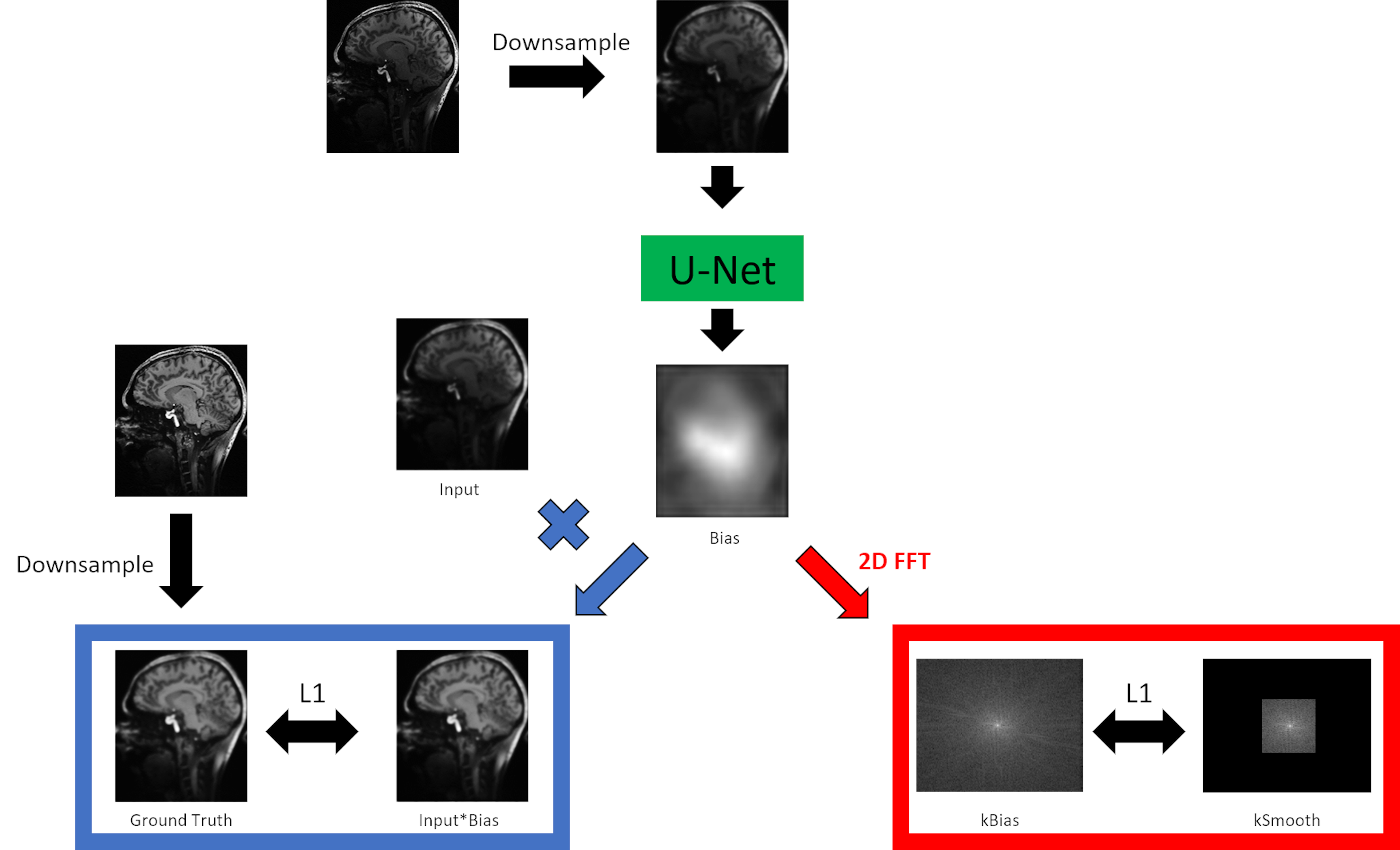
A U-Net-based7 deep learning network for B1 field correction was trained in a supervised fashion. Ground truth data was generated offline by applying UNICORN followed by SPM, or if UNICORN could not be easily applied only by SPM. Input to the network were uncorrected combined magnitude images, downsampled to 128x128. Output of the network was the bias field itself. An L1 loss was calculated between the ground truth data and the output bias field multiplied with the input. Additionally, a smooth loss was implemented in a way that the bias field was Fourier-transformed into k-space. This k-space (kBias) was compared in a L1 fashion to another k-space (kSmooth). kSmooth was generated from kBias by taking only the central 32x32 points and setting all other points to 0 (compare Fig. 1). This smooth loss was implemented to make sure that no anatomy is generated by DeepB1Fi. At last, a trade-off factor between those two losses was optimised. Training with PyTorch8 was run for 80 epochs on 2048 sagital slices from eight 3D T1 weighted 7T data sets using the ADAM optimizer9 with a learning rate of 0.01.pTx pulses were designed for the T1-weighted acquisitions as described in the FOCUS article2, for the T2-weighted acquisitions DiSCoVER10 was used, and for the diffusion-weighted acquisition slice individual RF shimming11 was employed.
Images were acquired on three different 7T MRI systems (all MAGNETOM Terra, Siemens Healthcare, Erlangen, Germany) placed in Glasgow (Diffusion), London (T2-weighted) and Erlangen (T1-weighted). The acquisitions in Erlangen and London were performed by using an 8Tx/32Rx brain coil (Nova Medical, Wilmington, MA, USA), in Glasgow a self-built 8Tx/32Rx brain coil was used12. All images were acquired using prototype sequences. Informed consent was obtained before each examination and the study was approved by the local ethics committee.
Results
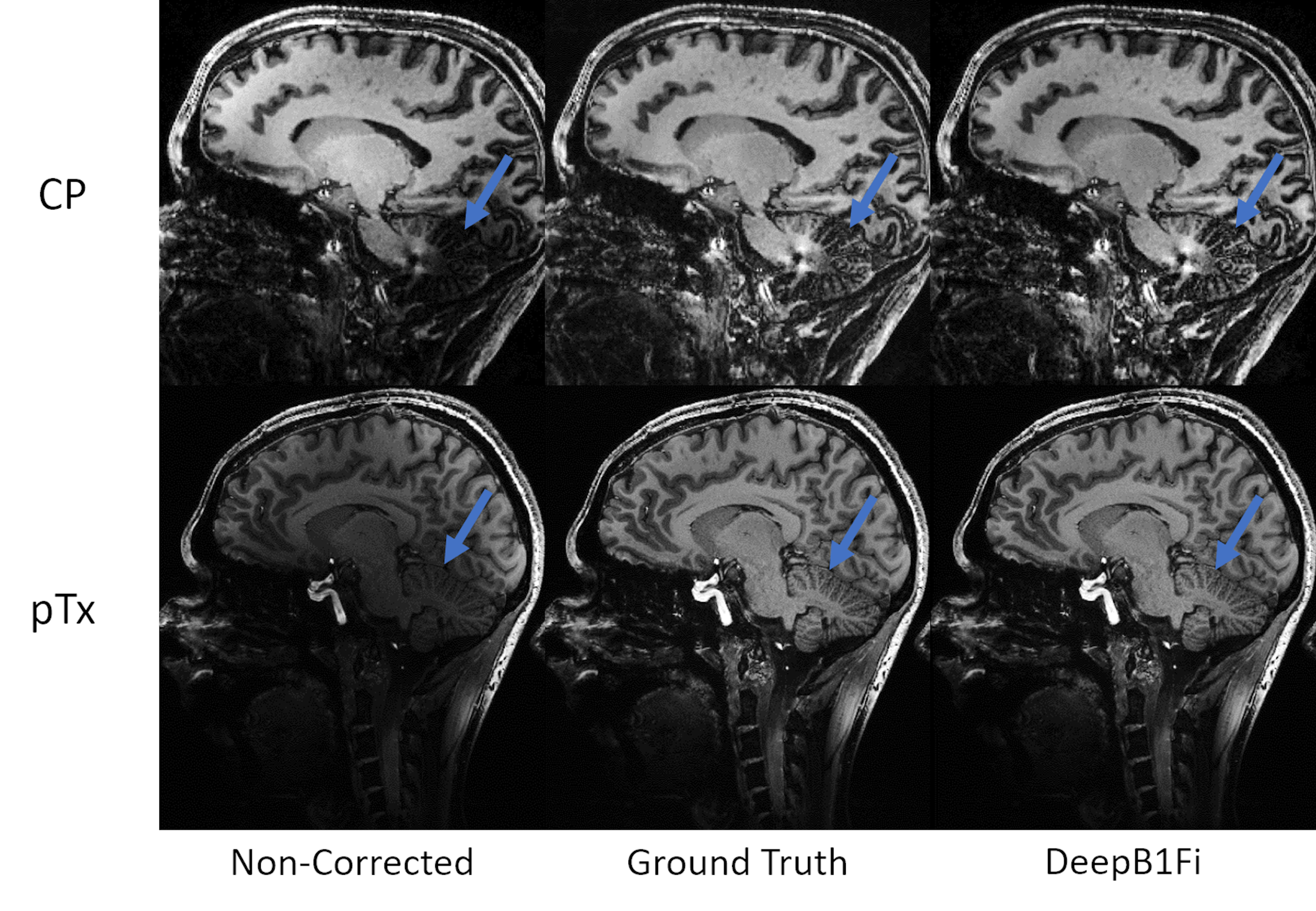
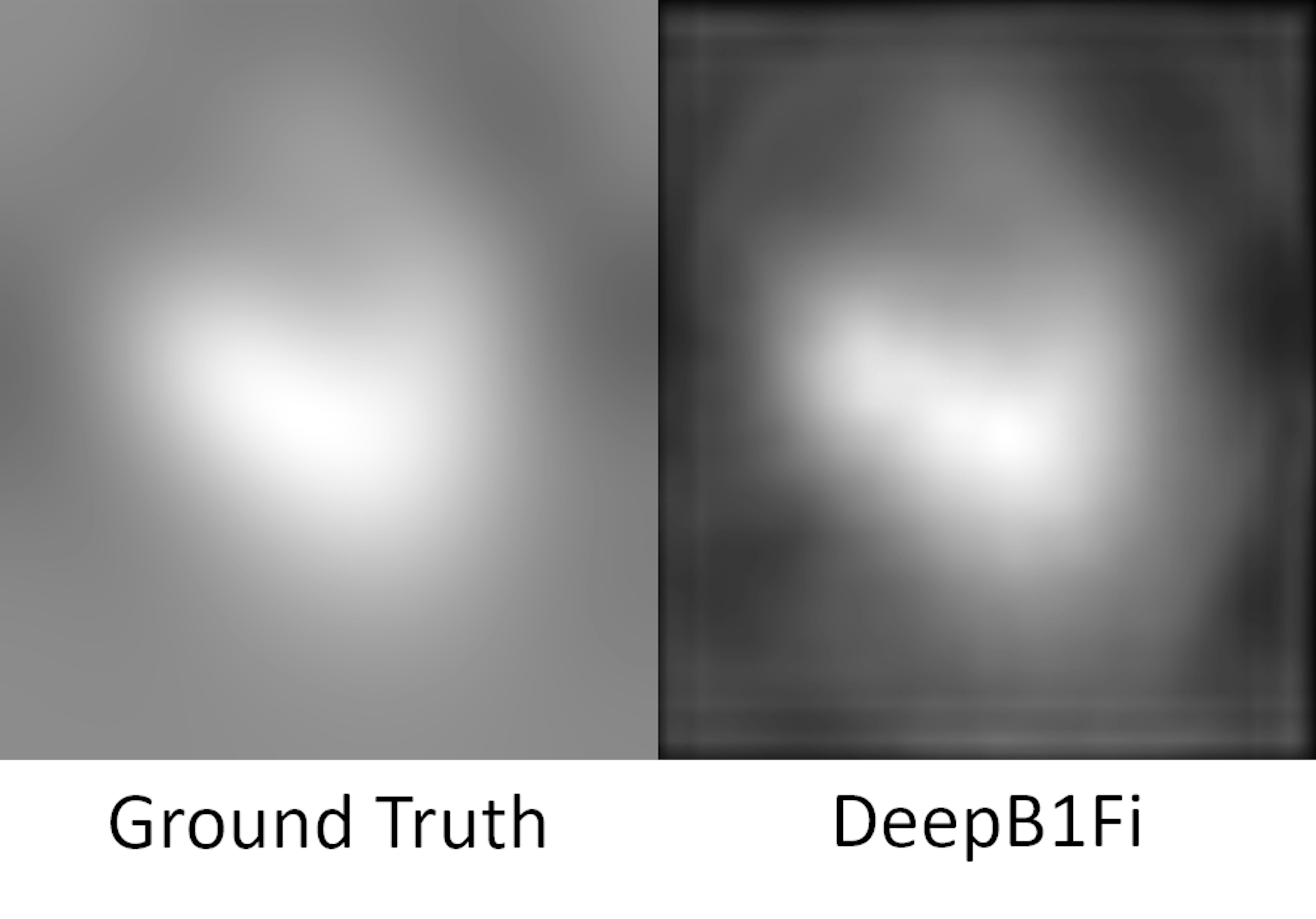
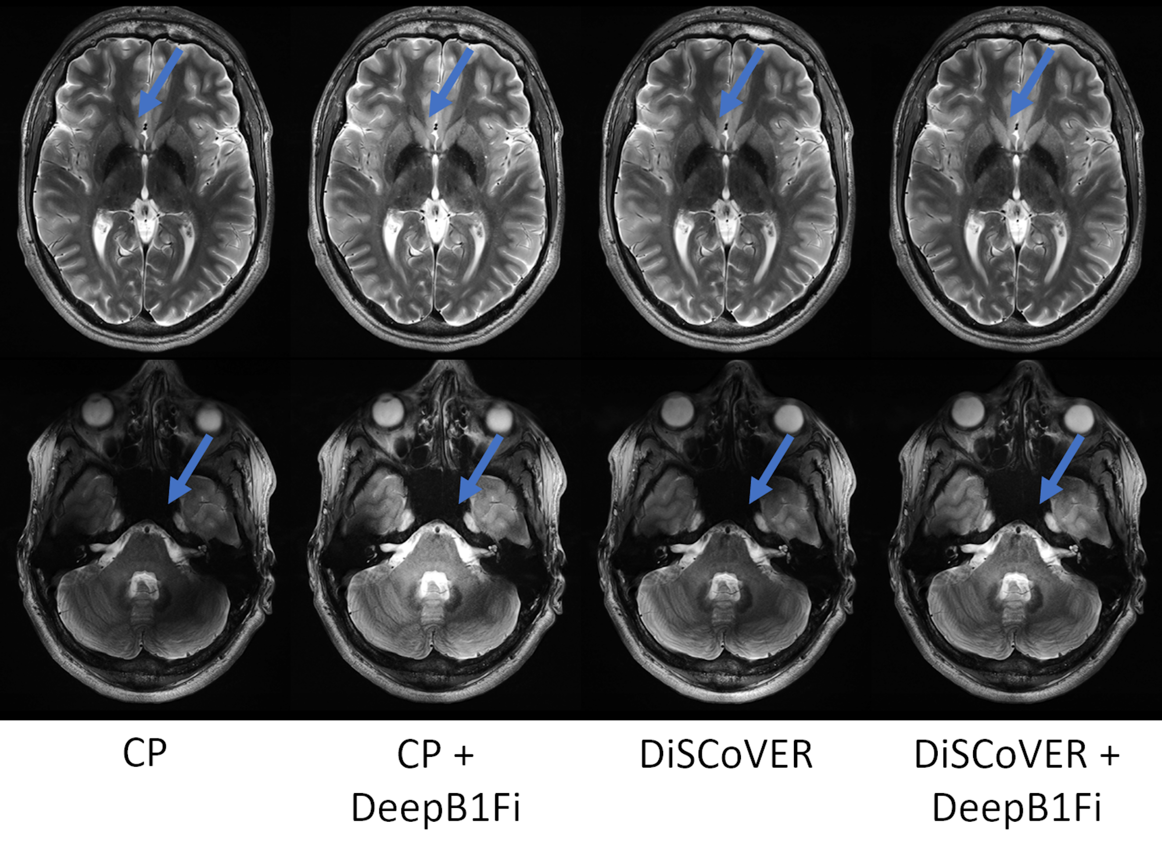
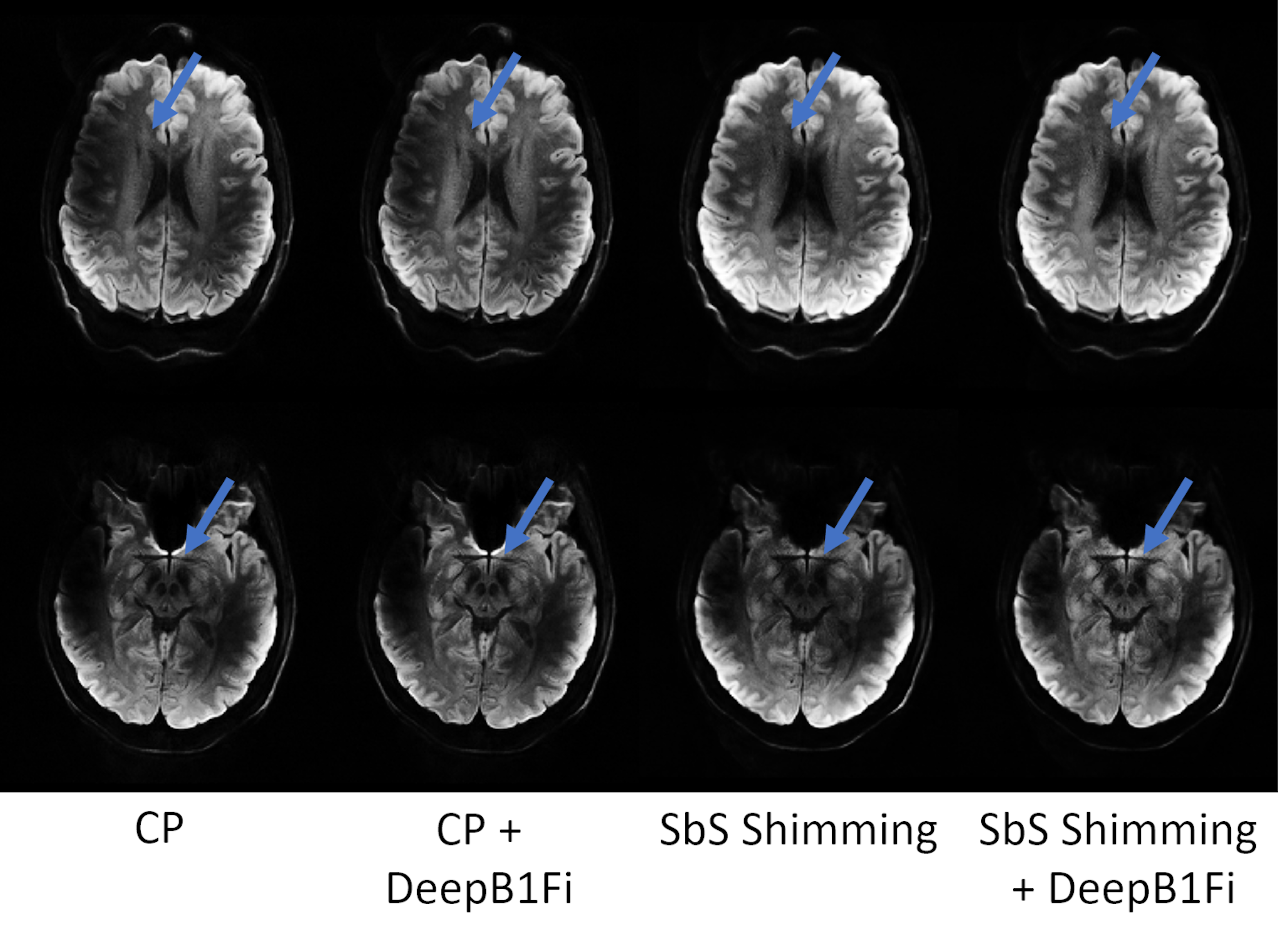
Figures 2 and 3 show that DeepB1Fi produces results comparable to the ground truth T1-weighted acquisition. These shown two data sets were not included in the training. To test the stability and generalizability of DeepB1Fi, it was subsequently applied to a T2 and diffusion-weighted acquisition (Figs. 4 and 5). These contrasts were not seen during training, reasonable results could still be generated. For the T2-weighted acquisition (Fig. 4) minor transmit inhomogeneities can be seen. In this case, DeepB1Fi also corrects successfully for the receive field. Applying DeepB1Fi to images acquired in circular polarisation (CP), the images show the expected central brightening. For the diffusion-weighted acquisition more transmit inhomogeneities can still be seen with the pTx acquisition. However, the receive field is corrected by DeepB1Fi.Inferencing took ~30ms per slice on a NVIDIA Quadro M2000 GPU adding up to a volume inferencing time for the T1-weighted acquisition of about 8 seconds. The SPM algorithm on the other hand took on the same workstation, about 6 min per volume on an Intel Xeon E5-2460 CPU.
Discussion
DeepB1Fi results exhibited image quality comparable to the ground truth methods in ~2% of the time. Additionally, it works well for different contrasts, even though the training data set was very limited. One limitation of DeepB1Fi is that it operates on a slice-by-slice basis. Thereby possible signal jumps can be introduced in the through-slice direction. This has not been observed here but needs to be considered. In principle this can be addressed by estimating the bias field on the entire 3D volume.Conclusion
These preliminary results showed that by combining pTx and DeepB1Fi homogeneous UHF brain images can be achieved. DeepB1Fi has the potential to implement bias field correction, the last missing puzzle piece for homogeneous UHF imaging, in a general and easy-to-implement way. DeepB1Fi achieves similar performance as the ground truth, while being about 45 times faster. Future work will extend DeepB1Fi to more contrasts and anatomies.Acknowledgements
No acknowledgement found.References
1. Gras, V., et al., Universal pulses: A new concept for calibration-free parallel transmission. Magn Reson Med, 2017. 77(2): p. 635-643.
2. Herrler, J., et al., Fast online-customized (FOCUS) parallel transmission pulses: A combination of universal pulses and individual optimization. Magn Reson Med, 2021. 85(6): p. 3140-3153.
3. Murakami JW, et al., Intensity correction of phased-array surface coil images. Magn Reson Med. 1996 Apr;35(4):585-90. doi: 10.1002/mrm.1910350419. PMID: 8992210.
4. Ashburner J, Friston KJ. Unified segmentation. Neuroimage. 2005 Jul 1;26(3):839-51. doi: 10.1016/j.neuroimage.2005.02.018. Epub 2005 Apr 1. PMID: 15955494.
5. Tustison, Nicholas J et al. “N4ITK: improved N3 bias correction.” IEEE transactions on medical imaging vol. 29,6 (2010): 1310-20. doi:10.1109/TMI.2010.2046908
6. Chebrolu VV, et. Al, Uniform combined reconstruction of multichannel 7T knee MRI receive coil data without the use of a reference scan. J Magn Reson Imaging. 2019 Nov;50(5):1534-1544. doi: 10.1002/jmri.26691. Epub 2019 Feb 19. PMID: 30779475.
7. Ronneberger, O., et. al, “U-Net: Convolutional Networks for Biomedical Image Segmentation”, arXiv:1505.04597v1 , 2015.
8. Paszke, A. et al., 2019. PyTorch: An Imperative Style, High-Performance Deep Learning Library. In Advances in Neural Information Processing Systems 32.
9. Kingma, D. P. et. al, “Adam: A Method for Stochastic Optimization”, arXiv:1412.6980v9 ,2014.
10. Tomi-Tricot, R., et al. Fully Integrated Scanner Implementation for Direct Signal Control for 2D T2-Weighted TSE at Ultra-High Field. in Intl. Soc. Mag. Reson. Med. 2021.
11. Williams, S.N., et al. Multi-Slice 2D pTx Readout-Segmented Diffusion-Weighted Imaging Using Slice-by-Slice B1+ Shimming. Proc. ISMRM & SMRT Annual Meeting & Exhibition, 15-20 May 2021.
12. Williams, S. N. ,et.al, A nested eight-channel transmit array with open-face concept for human brain imaging at 7 tesla. Frontiers in Physics, 9, 701330. (doi: 10.3389/fphy.2021.701330)
Figures