1377
Head Motion Tracking in MRI Using Novel Tiny Wireless Tracking Markers and Projection Signals1Department of Diagnostic Radiology, The University of Hong Kong, Hong Kong, Hong Kong, 2Department of Mechanical Engineering, The University of Hong Kong, Hong Kong, Hong Kong, 3Department of Medical Imaging, China Medical University Hsinchu Hospital, Hsinchu, Taiwan, 4Department of Radiology, School of Medicine, College of Medicine, China Medical University, Taichung, Taiwan, 5Department of Medical Imaging, China Medical University Hospital, Taichung, Taiwan, 6Department of Electrical Engineering, National Taiwan University, Taipei, Taiwan
Synopsis
Head motion is a significant problem for the challenging populations, and the wireless tracking coils has previously been proposed to enable prospective motion correction in MRI. In this study, we evaluated the tracking performance of a novel tiny wireless tracking marker by using a linear motion phantom, and tested the feasibility in omnidirectional 3D head motion tracking using three tiny wireless tracking markers. Both phantom and in-vivo results suggest that the novel tiny wireless tracking markers can provide good fidelity in 3D position tracking, with improved subject comfort and better flexibility in fixation of markers.
Introduction
Head motion is a significant problem during MRI scan, and the induced image artifacts can confound the interpretation for diagnosis. Therefore, the prospective motion correction has been proposed to address head motion problem during data acquisition, relying on real-time head position tracking using image-based navigators, optical tracking devices, or NMR markers1-3. The wireless tracking markers (or semi-active markers)2, 3 have been developed for tracking head position using MRI projection signals, without any needs of cable connections and additional receiver coils. Thus, wireless tracking markers are advantageous for prospective motion correction. However, the tracking accuracy and fidelity are limited by the size of wireless tracking marker3. Recently, a novel tiny wireless tracking marker4 has been developed for localizing interventional instruments within MRI. In this work, we first evaluated the tracking performance of this novel tiny wireless tracking marker by using a linear motion phantom, and then tested its feasibility in omnidirectional 3D head motion tracking.Method
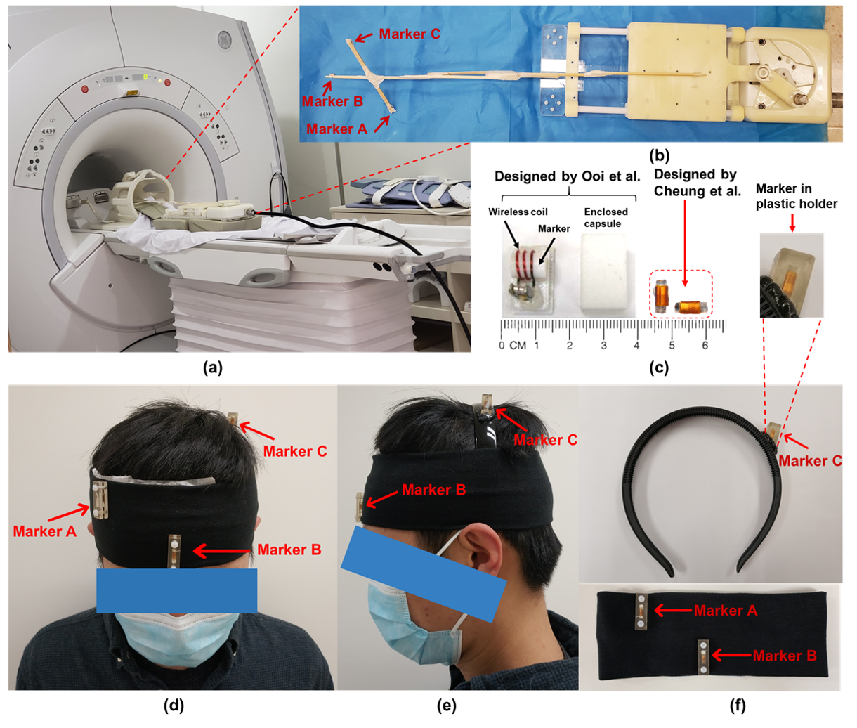
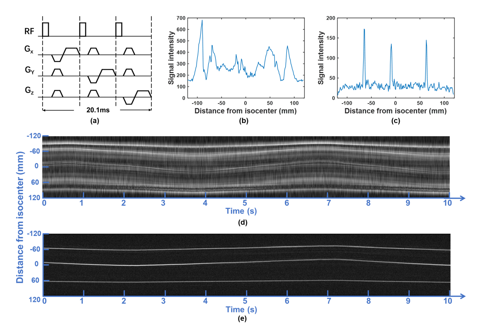
System setupAll experiments were performed on a 1.5T MRI scanner (Explorer, GE Healthcare) using an 8-channel head coil. Figure 1c shows the tiny wireless tracking marker composed of 1) wireless multi-layer tracking coils (6.7×1.5×0.3mm3), and 2) a cylindrical tube filled with 10mM Gd solution, which is much smaller than the design proposed by Ooi et al.2. Figure 2a shows the fast-tracking sequence used for acquiring three orthogonal projection signals from wireless tracking markers. A flip angle of 1° was used to minimize the excitation to brain tissue, and additional dephasing gradients were used to suppress residual background signal from brain tissue. Scan parameters included: TR=6.7ms/projection, TE=minimum, FOV=240mm, bandwidth=20kHz, sampling points=240. The intensity linear interpolation (ILI) method5 was employed to achieve more accurate extraction of marker positions from the projection signals.
Phantom experiments
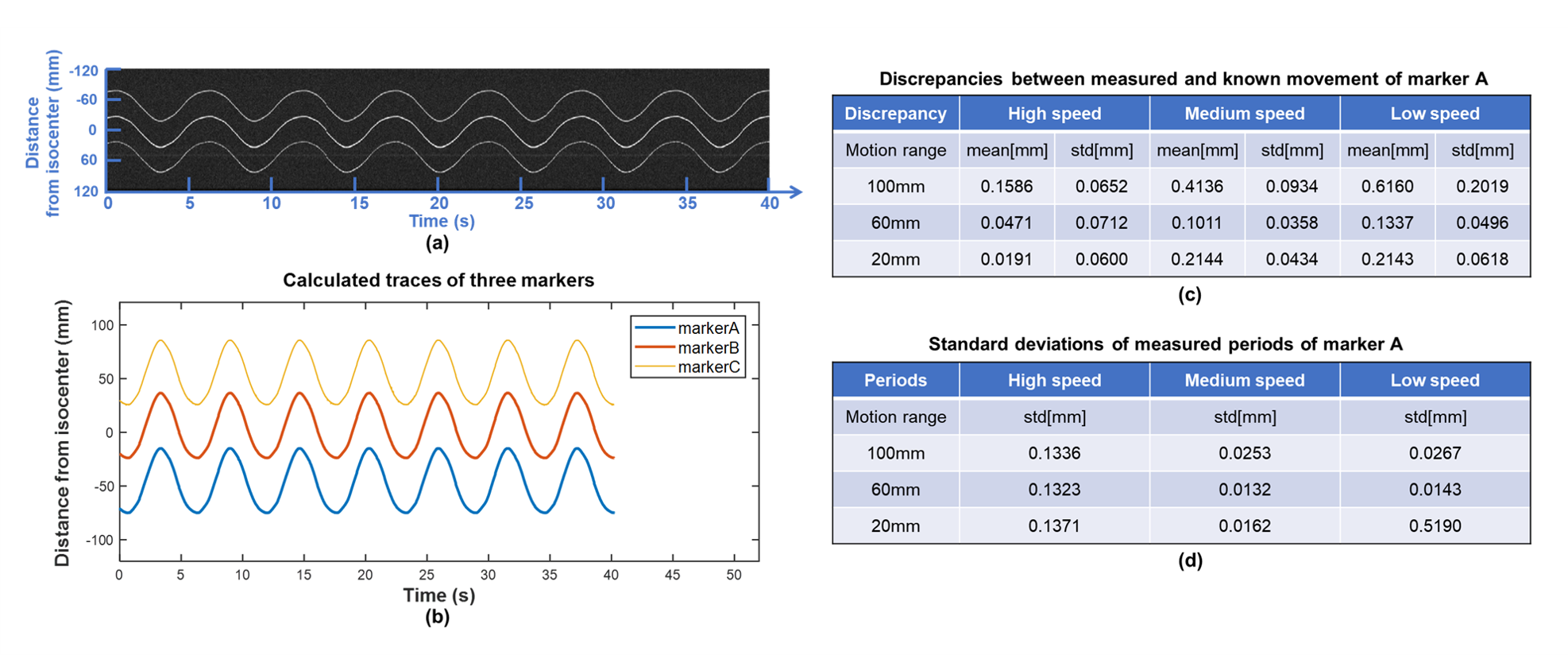
A motion phantom made of MR-compatible hydraulic motor6 was used to simulate periodic linear motion and evaluate tracking performance, with 3 different motion ranges (±50 mm, ±30 mm and ±10 mm) and 3 different moving speeds (high, medium, low) (Figs. 1a and 1b). Three tiny markers were stuck on a wooden rod, and then attached on the moving plate of motion phantom. A bottle of saline water was also placed inside head coil to simulate background signal. Projection data were acquired from 9 different motion settings (3 ranges × 3 speeds) with continuous sampling of 6 motion cycles for each setting. Discrepancies (mean ± std) between measured movement and known movement were calculated for assessing the accuracy of motion tracking. Standard deviations of measured periods from each cycle were also calculated.
In-vivo experiments
Marker fixation
Three wireless tracking markers were placed in plastic holders and then attached on a homemade head strap (Figs. 1d-1f), with careful design to avoid marker overlapping on three projection signals.
Evaluation of in-vivo tracking precision
To assess head tracking precision, 6000 repeated tracking scans were performed while the volunteer remained stationary. Although the respirations might induce slight head motion, tracking precision were roughly estimated using the stand deviation of 6000 measured positions.
In-vivo motion tests
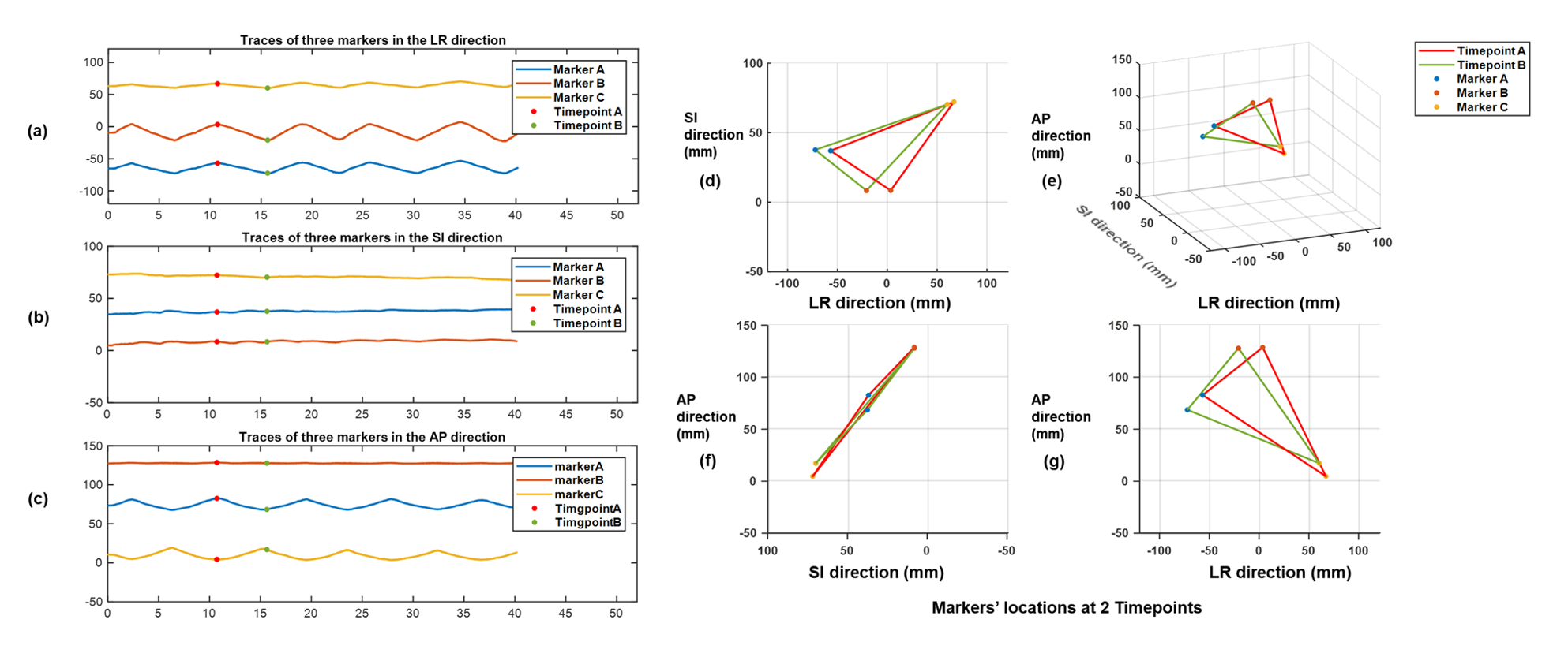
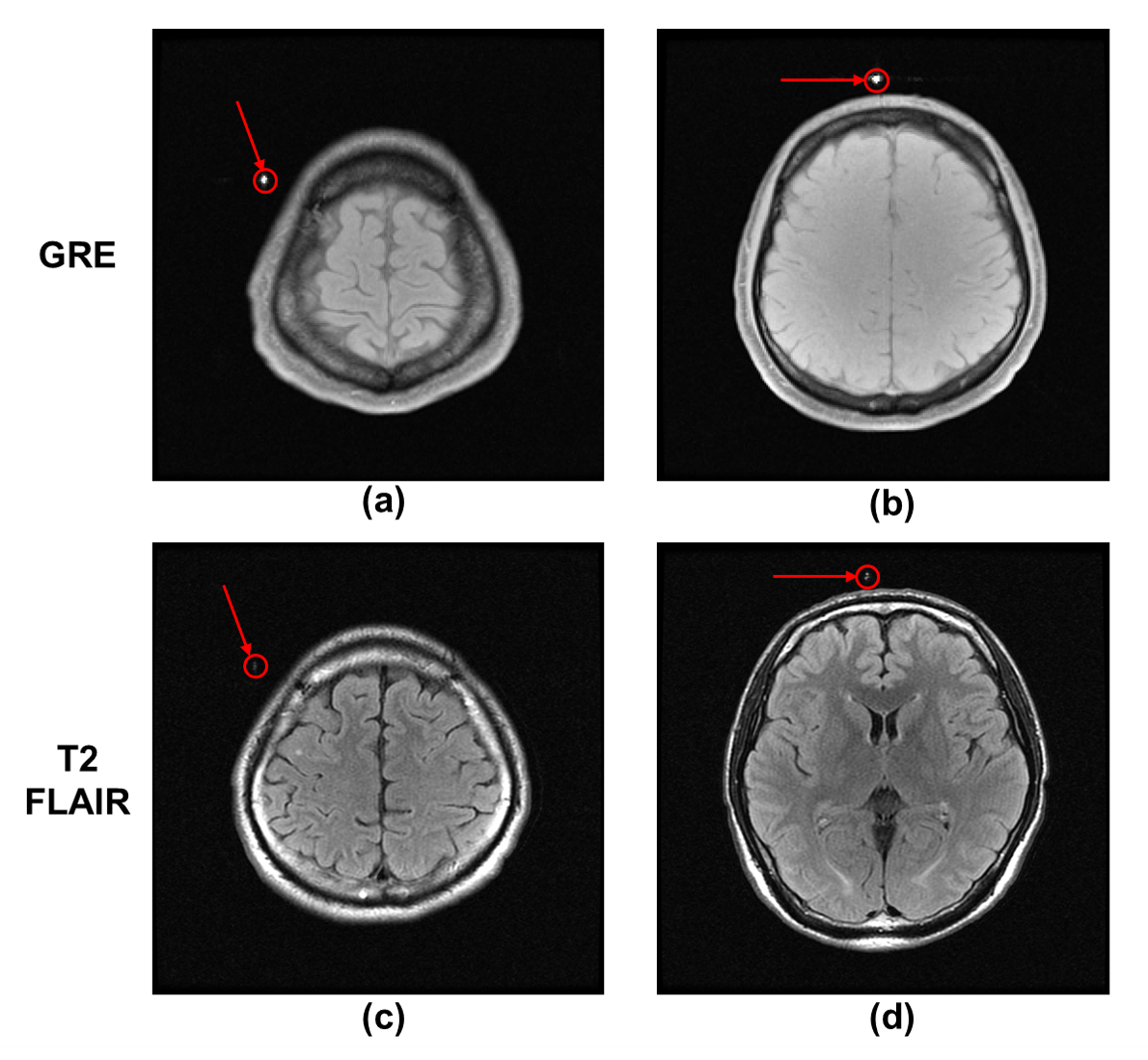
The volunteer was instructed to perform three different head motions: head shaking, head nodding, and tracking out a “figure of eight”7 with nose. Each motion was repeated during a 40-second scanning period. In addition, GRE and T2-FLAIR images were acquired when the volunteer remained stationary for evaluating the influence of wireless tracking marker to routine MRI imaging.
Results
Phantom experiments: Figure 3 shows the measured traces for 3 markers with ±30mm movement range at medium moving speed, and calculated discrepancies and periods for different motion settings. The mean and standard derivation of medium discrepancy were 0.1586mm and 0.0618mm, respectively.In-vivo experiments: Figure 2 shows successful suppression of background signal from brain tissue using dephasing gradients. Precision of motion tracking for the markers along LR, SI and AP directions were 0.1259mm(pixel), 0.0962mm(pixel), 0.0899mm(pixel), respectively. Figure 4a. shows measured traces for the motion of head shaking. Three markers positions at two selected time points were shown in Figure 4b. Traces of the other two motions were measured successfully with no marker overlapping. This can be explained by the small size of markers and improved flexibility of marker placements with the used of head strap. Figure 5 shows the routine MRI images without any influence from the markers (red arrows).
Discussion and Conclusion
Both phantom and in-vivo experiment results show good fidelity in motion tracking using the proposed tiny wireless tracking markers. The measured tracking accuracy and precision were satisfactory because the small size of marker can produce sharper peak signal for improving tracking accuracy. Localization of peak signal from the projection signal highly relies on the suppression of background signal using dephasing gradients. It is because dephasing gradients can produce substantial phase shift within a large volume while still keeping signal from small structure8. Therefore, the proposed tiny wireless tracking markers is less affected by the dephasing gradient and can provide better marker-to-background signal ratio. In conclusion, the proposed tiny wireless marker can provide good fidelity in omnidirectional 3D position tracking for prospective motion correction, with improved subject comfort and better flexibility in fixation of markers.Acknowledgements
The work was in part supported by grants from Hong Kong Research Grant Council (GRFs HKU17121517 and HKU17106820) and Hong Kong Innovation and Technology Commission (ITS/403/18).References
1. M. B. Ooi, S. Krueger, W. J. Thomas, S. V Swaminathan, and T. R. Brown, “Prospective real‐time correction for arbitrary head motion using active markers,” Magn. Reson. Med. An Off. J. Int. Soc. Magn. Reson. Med., vol. 62, no. 4, pp. 943–954, 2009.
2. M. B. Ooi, M. Aksoy, J. Maclaren, R. D. Watkins, and R. Bammer, “Prospective motion correction using inductively coupled wireless RF coils,” Magn. Reson. Med., vol. 70, no. 3, pp. 639–647, 2013.
3. S. Sengupta, S. Tadanki, J. C. Gore, and E. B. Welch, “Prospective real‐time head motion correction using inductively coupled wireless NMR probes,” Magn. Reson. Med., vol. 72, no. 4, pp. 971–985, 2014.
4. C.-L. Cheung, J. D.-L. Ho, V. Vardhanabhuti, H.-C. Chang, and K.-W. Kwok, “Design and Fabrication of Wireless Multilayer Tracking Marker for Intraoperative MRI-Guided Interventions,” IEEE/ASME Trans. Mechatronics, vol. 25, no. 2, pp. 1016–1025, 2020.
5. M. Rea, D. McRobbie, H. Elhawary, T. H. Zion, M. Lamperth, and I. Young, “Sub-pixel localisation of passive micro-coil fiducial markers in interventional MRI,” Magn. Reson. Mater. Physics, Biol. Med., vol. 22, no. 2, pp. 71–76, 2009.
6. Z. Dong et al., “High-performance continuous hydraulic motor for MR safe robotic teleoperation,” IEEE Robot. Autom. Lett., vol. 4, no. 2, pp. 1964–1971, 2019.
7. M. Herbst, J. Maclaren, M. Weigel, J. Korvink, J. Hennig, and M. Zaitsev, “Prospective motion correction with continuous gradient updates in diffusion weighted imaging,” Magn. Reson. Med., vol. 67, no. 2, pp. 326–338, 2012.
8. C. L. Dumoulin, R. P. Mallozzi, R. D. Darrow, and E. J. Schmidt, “Phase‐field dithering for active catheter tracking,” Magn. Reson. Med., vol. 63, no. 5, pp. 1398–1403, 2010.
Figures