0004
Low-Angle Combined-Echo (LACE) Imaging in Highly Inhomogeneous B0 Magnetic Fields1Biomedical Engineering, Columbia University, New York, NY, United States, 2Department of Radiology and Biomedical Imaging, Magnetic Resonance Research Center, Yale University School of Medicine, New Haven, CT, United States, 3Radiology, Columbia University Medical Center, New York, NY, United States
Synopsis
In line with recent developments in scanner design for more cost effective and more accessible scanners, we propose a low-angle combined-echo sequence similar to a conventional spin echo sequence capable of producing high quality images in the presence of strong B0 inhomogeneity. We present simulation results investigating the signal dependence on the sequence’s timings and flip angles as well as image contrast for typical relaxation times of normal brain white and gray matter. The simulations were validated in vivo at 4 T. Lastly, we show the feasibility to utilize multi-coil generated image encoding fields for this sequence.
Introduction
In recent years, a variety of new approaches to scanner design have been presented aiming to lower the costs of MRI and to increase accessibility. One of these approaches is relaxing the homogeneity requirements for the main B0 magnetic field from typically less than a few hundred hertz to 20 kHz (equivalent to a few ppm to 300 ppm at 1.5 T) or more across the volume of interest in a recently proposed 1.5 T head-only scanner to reduce scanner cost1. This development necessitates the design of MRI pulse sequences robust against these conditions. Here we present a low-angle combined-echo (LACE) sequence capable of producing high quality images in the presence of strong B0 inhomogeneity.Methods
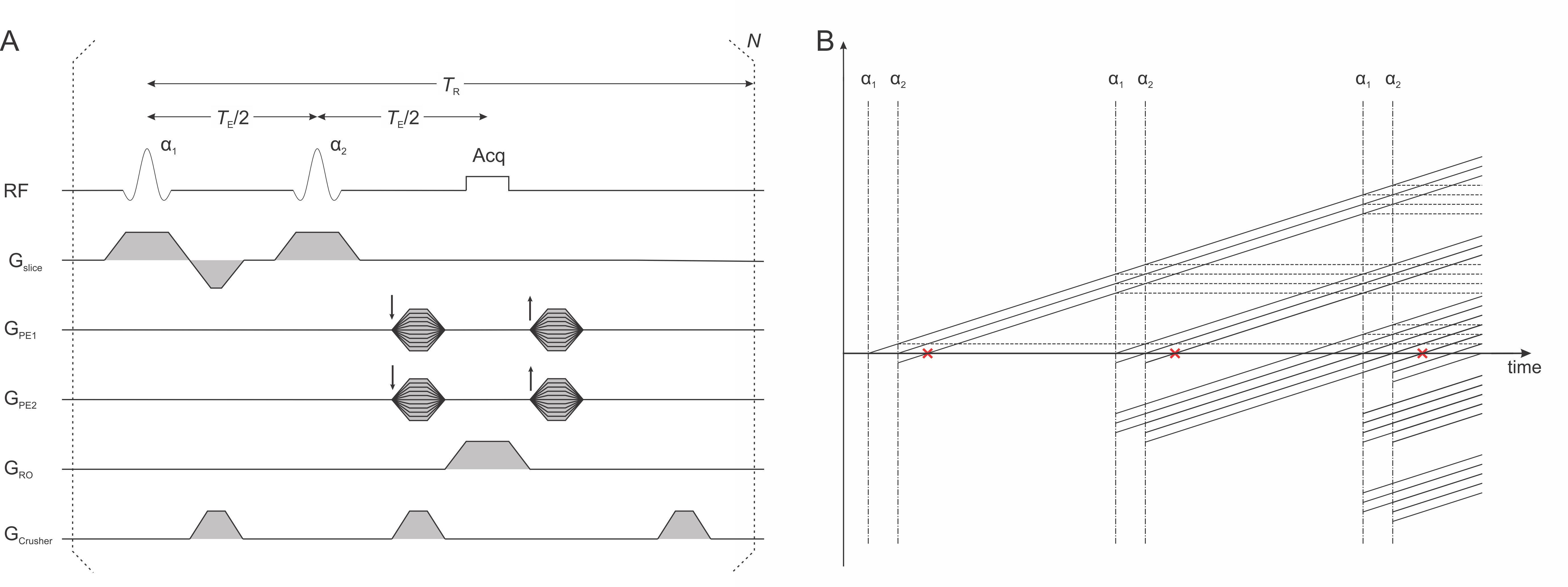
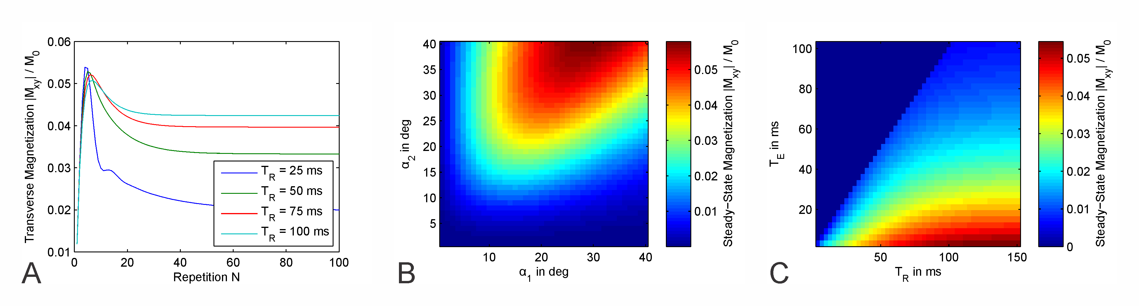
The proposed LACE sequence is, similar to a conventional spin echo sequence, based on two broadband radio-frequency pulses separated by the time $$$T_E/2$$$, signal readout at the time of the echo $$$T_E$$$ and a delay to complete the repetition time $$$T_R$$$. With the use of short $$$T_R$$$ delays, the echo formed at steady-state contains both spin echo and stimulated echoes (Figure 1). Simulations based on the product operator formalism2 were performed in MATLAB (MathWorks, Natick, MA, USA) to investigate the dependence of the signal strength on the sequence parameters. The transverse magnetization was simulated at flip angles $$$\alpha_1/\alpha_2\leq40^\circ$$$, $$$T_E\leq100\,\mathrm{ms}$$$ and $$$T_R\leq150\,\mathrm{ms}$$$. The simulations have been performed with two combinations of $$$T_1$$$ and $$$T_2$$$ values ($$$T_1/T_2=900/50\,\mathrm{ms}$$$ and $$$1400/60\,\mathrm{ms}$$$) representing experimentally determined values for human brain white and gray matter (WM/GM) at 4 T.To validate the simulation results, in vivo brain images were acquired from 6 healthy subjects on a 4 T Bruker scanner at the Yale MR Research Center (MRRC) with the following sequence parameters: $$$T_E=12\,\mathrm{ms}$$$, $$$T_R=100\,\mathrm{ms}$$$, AFPST4 pulse excitation (1 ms) with 20 kHz bandwidth, readout bandwidth BWRO = 100 kHz. A paper clip was fixed to the bottom of the head rest below the subjects’ head to validate the B0 insensitivity of the MRI sequence at hand. The proposed 1.5 T head-only scanner will be equipped with a multi-coil (MC) array3 instead of linear gradient coils for the generation of image encoding fields1,4, therefore, we also tested LACE with MC generated encoding fields similar to previous work5.
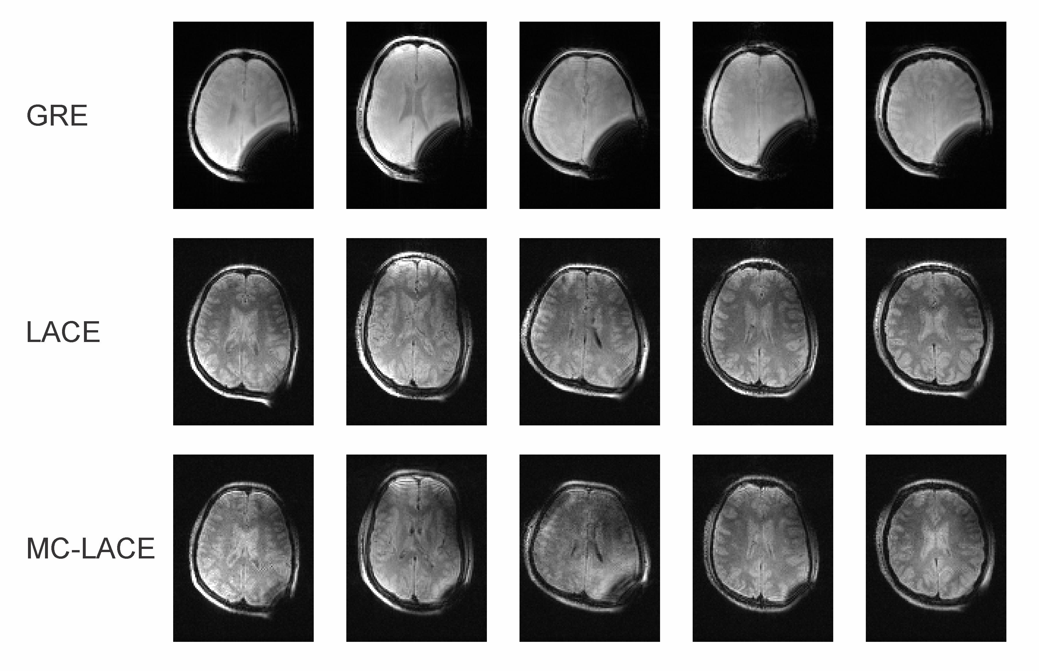
Results
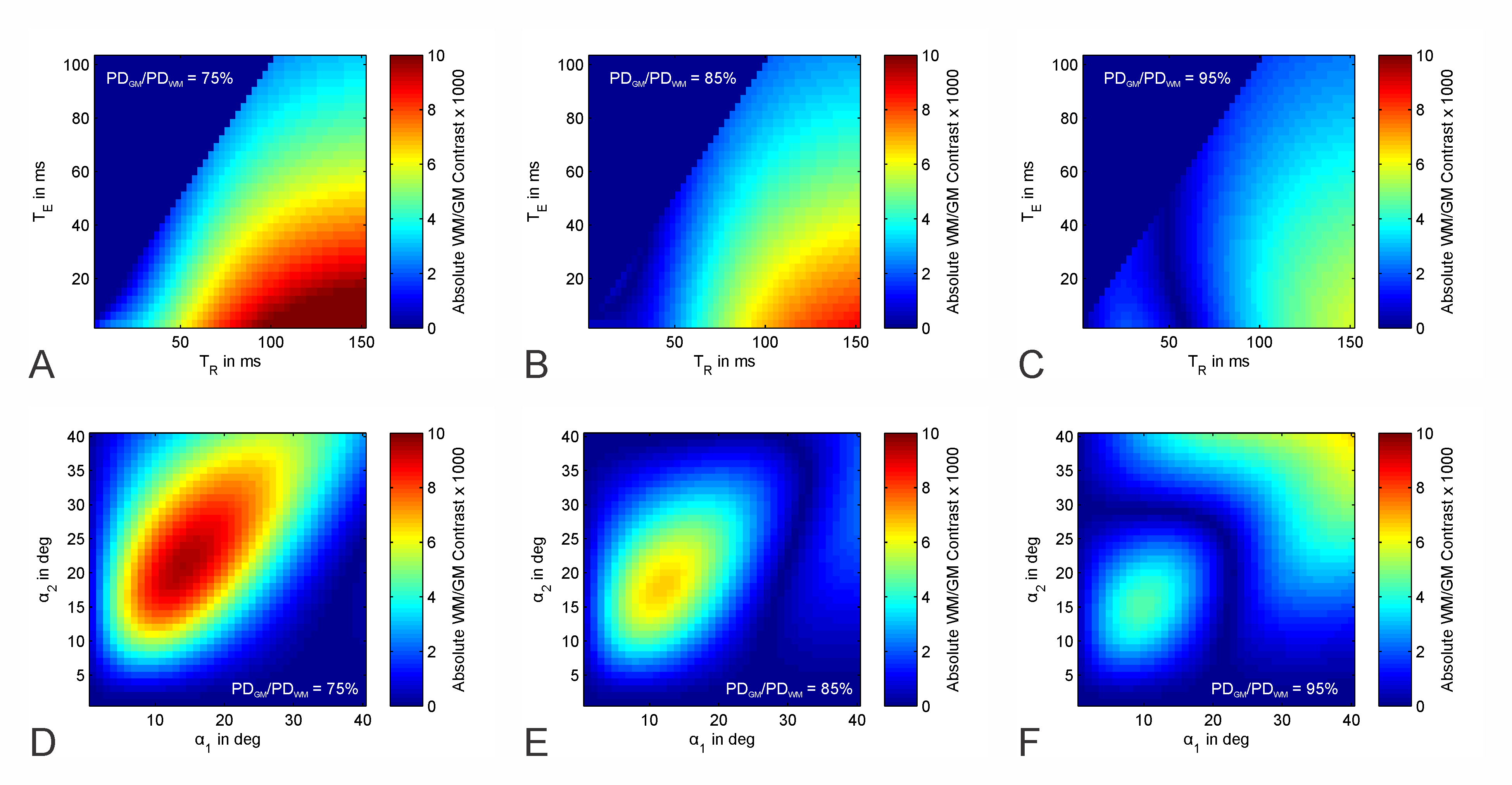
The simulations show the transverse magnetization rapidly increases in the first few repetitions of the sequence and after reaching a maximum slowly decreases to a steady-state (Figure 2A). The steady-state magnetization is larger if α2 is larger than α1, and in general combinations of larger flip angles lead to a stronger steady-state magnetization, with a maximum in the investigated range around $$$\alpha_1/\alpha_2=30^\circ/40^\circ$$$ (Figure 2B). Steady-state magnetization increases with longer $$$T_R$$$ and shorter $$$T_E$$$ (Figure 2C).Absolute contrast between GM and WM, calculated as the absolute difference between the steady-state transverse magnetization of the two sets of $$$T_1/T_2$$$ values, was found to be stronger with shorter $$$T_E$$$ and longer $$$T_R$$$ in general. There is an area of low contrast for intermediate values of $$$T_R$$$ whose location is dependent on the relative proton density $$$PD_{GM}/PD_{WM}$$$ between the two tissues (Figure 3A-C). A region of high contrast is evident when mapping it against the flip angles $$$\alpha_1/\alpha_2$$$. While the shape and strength of that area differ with relative PD, small flip angles around $$$\alpha_1=10^\circ$$$ and $$$\alpha_2=15^\circ$$$ should always yield good contrast (Figure 3D-F).
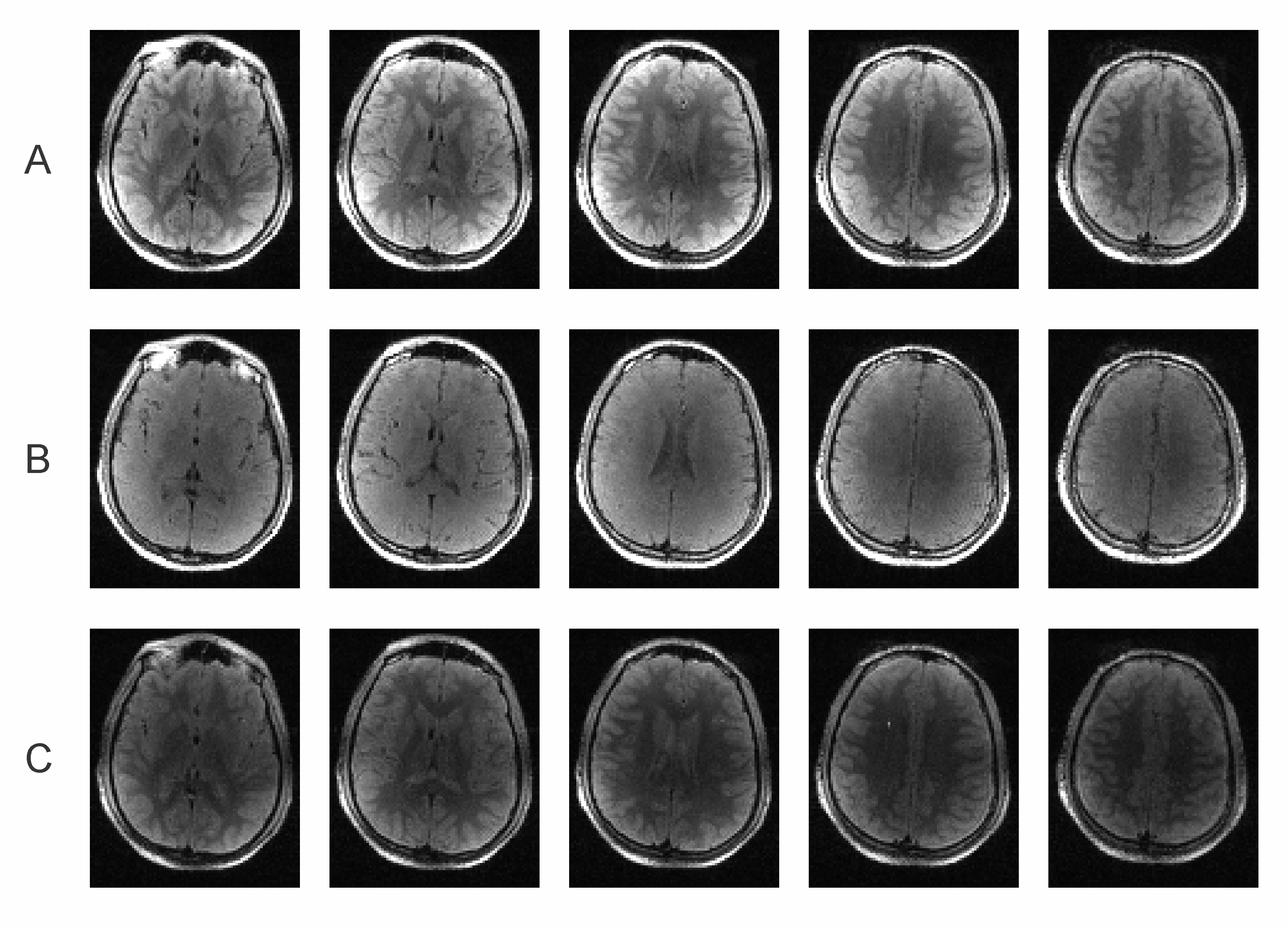
Brain images acquired in vivo match the simulated contrast behavior when assuming a relative PD of about 85% with images at $$$\alpha_1/\alpha_2=10^\circ/20^\circ$$$ showing good contrast with $$$T_E/T_R=12/100\,\mathrm{ms}$$$, but images acquired at $$$\alpha_1/\alpha_2=10^\circ/40^\circ$$$ or with $$$T_R=50\,\mathrm{ms}$$$ showing only little contrast (Figure 4). The latter case also shows reduced signal intensity, in line with Figure 2C. While the B0 inhomogeneity induced by the paper clip effects large portions of a 3D gradient echo scan acquired for reference, LACE imaging is able to recover the signal in this area. LACE images acquired with MC generated encoding fields show largely the same image quality than the ones acquired with regular gradients (Figure 5). Mismatches between regular LACE and MC-LACE images are likely due to non-linearities in the MC encoding fields at the edge of the FoV.
Discussion
LACE MRI enables imaging in the presence of strong B0 inhomogeneity by utilizing high bandwidth RF pulses and selecting combined spin- and stimulated echoes. The overall signal intensity is ~20% of a low-angle gradient-echo sequence (e.g. FLASH, calculated with the Ernst equation6 at flip angle 15°) and is comparable to that of a recently described MP-SSFP method7. High GM/WM image contrast can be achieved with modest nutation angles, providing a low-power alternative to high-powered spin-echo-based methods (e.g. 3D FSE). Even though employing larger flip angles generates more signal, sufficient signal can be acquired at low flip angles with good GM/WM contrast. If the background B0 field behavior is known, as it is the case for a given main magnetic field, the resulting image distortions can be corrected. Utilizing lower flip angles enables larger bandwidth RF pulses that are necessary to excite all spins in the presence of large off-resonances without exceeding SAR constraints. With only two excitation pulses the described sequence is rather simple and should be straightforward to implement in any MRI system.Acknowledgements
This research was supported by the National Institute of Biomedical Imaging & Bioengineering of the National Institutes of Health under award number U01EB025153.References
1. Garwood M, Mullen M, Kobayashi N, et al. A compact vertical 1.5T human head scanner with shoulders outside the bore and window for studying motor coordination. Proc Intl Soc Magn Reson Med. 2020;28:1278.
2. Sørensen OW, Eich GW, Levitt MH, Bodenhausen G, Ernst RR. Product operator formalism for the description of NMR pulse experiments. Prog Nucl Magn Reson Spectrosc. 1984;16:163-192.
3. Juchem C, Nixon TW, McIntyre S, Rothman DL, de Graaf RA. Magnetic field modeling with a set of individual localized coils. J Magn Reson. 2010;204(2):281-289.
4. Theilenberg S, Shang Y, Kobayashi N, Parkinson B, Juchem C. Multi-Coil Array for Combined Imaging and B0 Shimming in a Portable Head-Only Scanner. Proc Intl Soc Magn Reson Med. 2019;27:1480.
5. Juchem C, Theilenberg S, Kumaragamage C, et al. Dynamic multicoil technique (DYNAMITE) MRI on human brain. Magn Reson Med. 2020;6(84):2953-2963.
6. Ernst RR, Bodenhausen G, Wokaun A. Principles of Nuclear Magnetic Resonance in One and Two Dimensions. Oxford: Clarendon Press; 1987:610.
7. Kobayashi N, Parkinson B, Idiyatullin
D, et al. Development and validation of 3D MP‐SSFP to enable MRI in
inhomogeneous magnetic fields. Magn Reson Med. 2020;85(2):831-844.
Figures